Evaluating Foundation Model Robot Pose Estimation with Synthetic Data Generation
1. Introduction
Position and Orientation or "Pose" is a 4x4 matrix that defines the translation or "position" and rotation or "orientation" of an object. One reason to care about Robot Pose Estimation is because accurate prediction of the two pose matrices for the robot and an object, enables calculation of a "relative grasp" transform that describes how the robot should position itself to grasp the object successfully.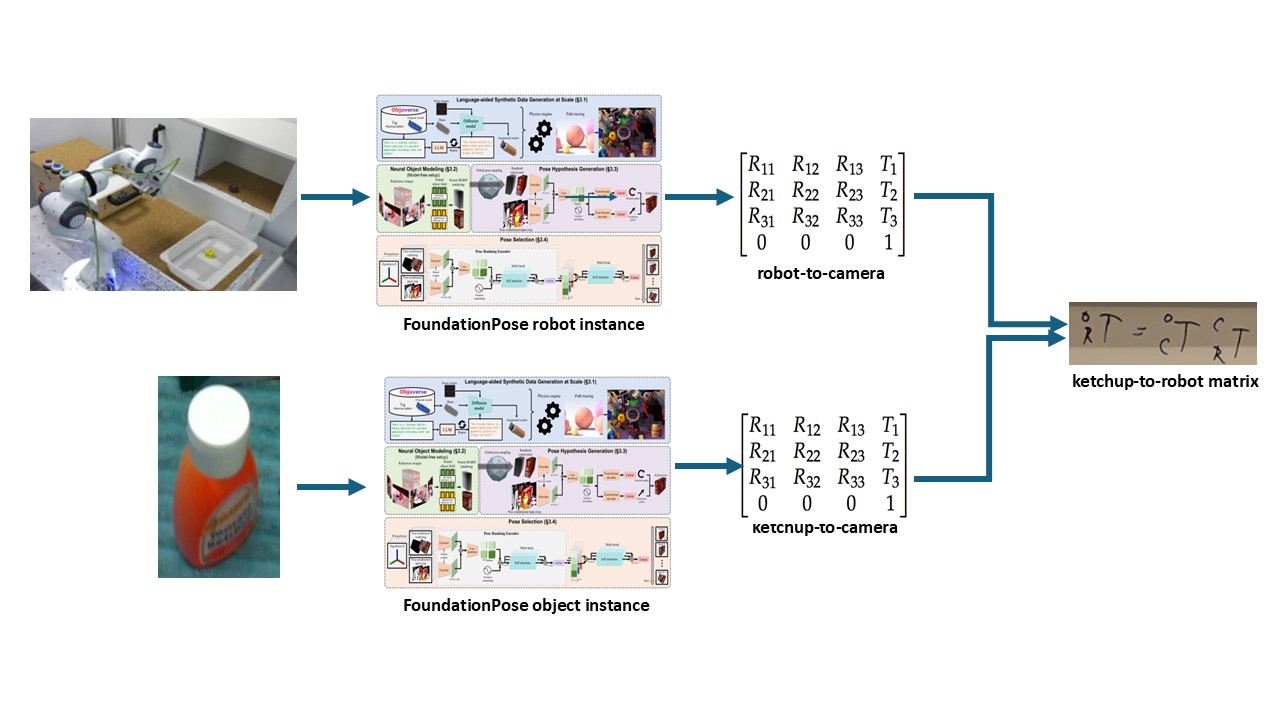 $$T_R^O = T_C^O \times T_R^C$$ $${T_C^R}^{-1} = T_R^C$$ If you can perform accurate robot pose estimation using a foundation model. You should be able to grasp items that the model wasn't trained on with robots the model wasn't trained on, by leveraging the powerful open-vocabulary capabilities of foundation models that were pretrained on massive datasets. The team that built FoundationPose had already proven it could work on household objects such as a mustard bottle and a driller. Proving that the foundation model, FoundationPose has this "Open-Vocabulary" capability on robot data it hadn't seen was my goal. I will briefly cover FoundationPose's architecture and training details, but for more, please refer to the original work: FoundationPose
2. Model Architecture
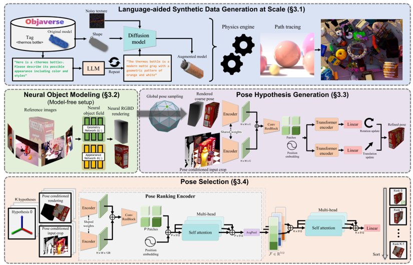
2.1 Language-aided Synthetic Data Generation at Scale
- Rendered 5 million images of 41k CAD models from Objaverse
- Prompted ChatGPT --> describe possible appearance of object
- Prompted Diffusion Model --> texture synthesis
2.3.1 Pose Initialization
- Initialize translation by running out of box object detection on the object and picking a 3D point in middle of BB and median depth distance away.
- Initialize rotation by sampling viewpoints from icosphere and augmenting with discrete rotations.
- Take the coarse pose guess and render the image of the object with that guess.
- Get the real rendered image.
- Network trained on ∆t and ∆r between coarse guess and rendered image with refinement loss below.
- The Pose Refinement Network outputs an F alignment score vector per guess that describes the alignment between the refined guess from above and the real rendered image.
- Concatenate all F alignment score vectors per guesses. Linear project this vector to S. Perform multi-headed self attention on this vector so the guesses can compare with each other to see who is more aligned.
- Select the pose with highest score as final prediction.
- Train the pose selection network with the Triplet Loss below which penalizes bad guesses and doesn't penalize good guesses.
3. Synthetic Robot Data Generation
Now that we have an idea of how the model was trained, let's get back to what I actually did. In order to predict pose correctly, FoundationPose needs several data inputs:- RGB, Depth, Binary Mask Frames
- CAD Model
.obj - Camera Intrinsics Matrix
In addition, for evaluation purposes we also need:
- Camera Frame Pose Annotations (Ground Truth)
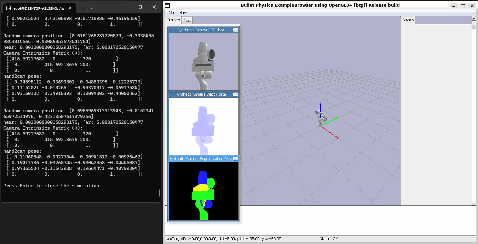
I generated this data inside Pybullet by setting up the robot and a virtual camera inside Pybullet. I defined the virtual camera through a view matrix and a projection amtrix. The view matrix defines the world coordinates to camera coordinates transform while the projection matrix defines the 3D camera coordinates to 2D image coordinates transform. I then took photos of the robot rotating around a sphere. Next, I calculated the grouth truth robot pose annotations by getting the world frame pose, and using the view matrix which is basically the camera extrinsics which is a transform that defines world frame to camera frame to transform to camera frame pose. I also used the projection matrix to transform to image coordinates in order to actually visualize the ground truth pose annotations on our image data.
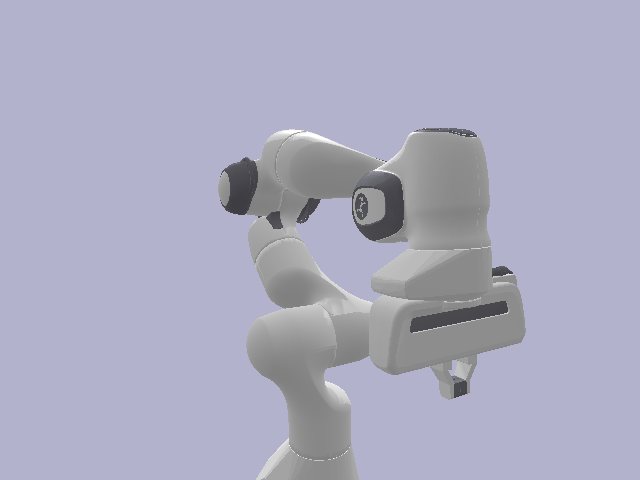
- Rendering a Robot inside of Pybullet:
robot_id = p.loadURDF(robot.urdf) - Setting up a Virtual Camera and taking Images of the Robot:
view_matrix = p.computeViewMatrix(camera_position, target_point, up_direction)
projection_matrix = p.computeProjectionMatrixFOV(fov=60, aspect=(w/h), nearclip, farclip)
image = p.getCameraImage(w, h, view_matrix, projection_matrix) - Getting Grouth Truth Pose Annotations:
robot_world_pose = p.getLinkState(robot_id, link_index)
robot_camera_pose = view_matrix.T @ robot_world_pose
pose_image_coordinates = projection_matrix.T @ robot_camera_pose
Pybullet Synthetic Data Generation


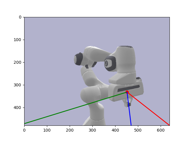
4. Evaluation
Now, with my Synthetic Data, all that was left to do was to run FoundationPose on and get the robot pose estimates for my synthetic data. Once I had these predictions, I then evaluated against the pose annotations I generated earlier. However, there was one last additional transform I needed to perform here to make the poses line up reasonably. After much searching, I found that Pybullet follows the OpenGL coordinate system which defines the Y and Z axes to the inverse of how OpenCV defines them. Our foundation model or FoundationPose follows the OpenCV system while our synthetic data follows the OpenGL system. I therefore had to run my annotations through one last transform where I inversed the Y and Z axes so our pose predictions and annotations lined up reasonably well. Finally, I evaluated the Translation component of the pose with Euclidean Distance and the Rotation component with Angular/Geodesic Error. I got reasonably good results with translation error being less than 1mm off and rotation being less than 1 degree off.
Rotation Error: 0.674°
Translation Error: 0.655 mm